Simple and powerful F.M. Receiver Communication in F.M. band is easy, less
expensive and has many more advantage.
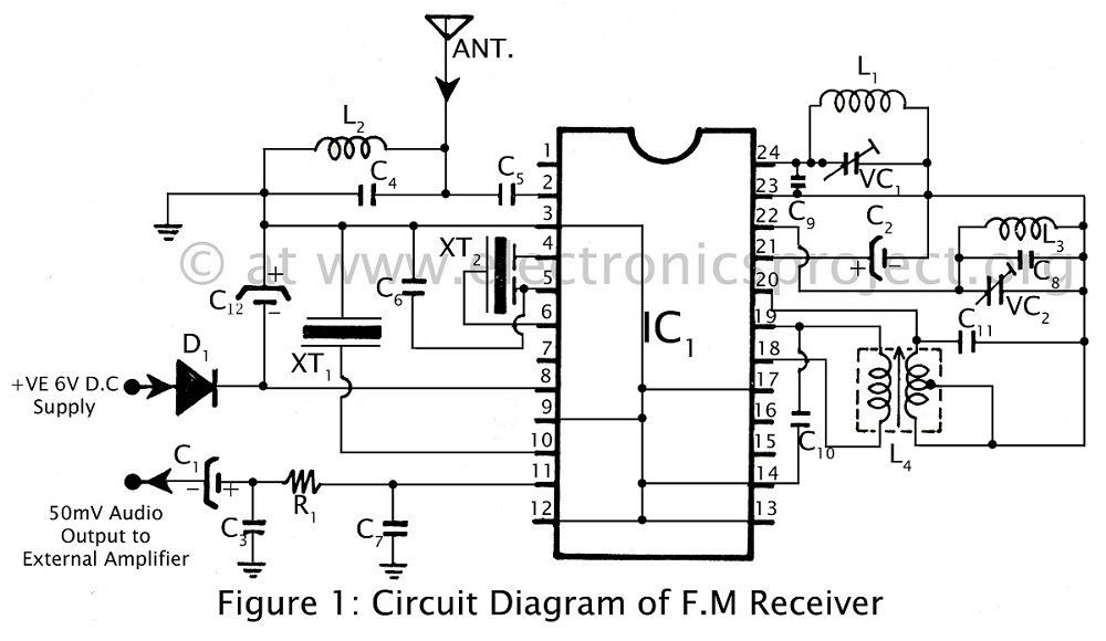
As we have already published Simple F.M. transmitter circuit in previous article. Now, here is a circuit diagram with description of Powerful F.M. receiver using single IC used to receive frequency range of 88 MHz to 108 MHz in F.M. band. You can also use F.M. receiver circuit in radio, tape recorder,
stereo etc.
Circuit Description
simple and powerful F.M. receiver With the circuit described here (F.M.
receiver) one can easily receive F.M. signal
and is build around IC TEA5591 (IC1). Transmitted F.M. R.F. signal is received by
telescopic antenna and is given to pin 2 of
IC1 passes though band pass filter made from coil L2 and capacitor C4. R.F. signal given to IC1 is amplified and is tuned with the help of capacitors C9, C13 and coil L1. Coil L3 with capacitors C8 and C14 is configured as oscillator and its output is
given to pin no 22 and 23 of IC1 in order obtain IF frequency by mixing with tuned
R.F. frequency. Tuned IF frequency of 10.7
MHz is obtained from amplifier made from
coil L4 and capacitors C10 & C11. Ceramic filter XT1 and XT2 is used to filter IF frequency and is given to pin no 4 of IC1. Internal detector stage is used to detect
F.M. signal. Finally output from F.M.
receiver is obtained from pin 11 and is given
to audio amplifier stage. PARTS LIST